Before information can be transmitted using a digital modulation scheme, the information bits have to be mapped to the constellation (What is a constellation?). Each point in the constellation is known as a symbol, making the full collection of symbols a kind of alphabet of the modulation scheme. For most digital modulation schemes, each symbol carries more than one bit. This implies that a (fixed) number of information bits must be “assigned” to each symbol in a process called mapping.
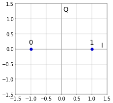
The complex signal that leads to the figures at the end of the article What is a Constellation Diagram? is called a baseband signal. For BPSK, this baseband signal is simply a series of complex values taken from the set \(\{1, -1\}\). These complex values are the symbols of BPSK. The figures at the end of What is a Constellation Diagram? use the set \(\{i, -i\}\) for BPSK. This is completely equivalent, since it is just a rotation of the constellation by 90 degrees. However, typically \(\{1, -1\}\) is used (although it must be said that using \(\{i, -i\}\) makes it easier to not forget that the signal should always be treated as complex in this context, even though the values happen to be real). This makes mapping bits to BPSK simply
\[\begin{array}{ccc}
\mathrm{bit}&&\mathrm{symbol}\\[0.3em]
0&\rightarrow&-1\\[0.1em]
1&\rightarrow&+1
\end{array}\]
This is illustrated graphically in Figure 1.
 Figure 1. Bit mapping for BPSK.
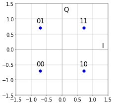
For QPSK, two bits are encoded in each symbol, according to the following table.
\[\begin{array}{ccc}
\mathrm{bits}&&\mathrm{symbol}\\[0.3em]
00&\rightarrow&-\sqrt{2}/2-i\sqrt{2}/2\\[0.1em]
01&\rightarrow&-\sqrt{2}/2+i\sqrt{2}/2\\[0.1em]
10&\rightarrow&+\sqrt{2}/2-i\sqrt{2}/2\\[0.1em]
11&\rightarrow&+\sqrt{2}/2+i\sqrt{2}/2
\end{array}\]
This is illustrated in Figure 2.
 Figure 2. Bit mapping for QPSK.
Even if this whole mapping thing seems trivial, there is a crucial remark to be made. An obvious way to do the mapping is to simply put the sequence \(00, 01, 10, 11\) in the constellation, either clockwise or counterclockwise. However, this is not how it’s done in Figure 2, which uses so-called Gray coding (after Frank Gray, so there is no American/British spelling choice to be made here). Without going into details, the mapping of Figure 2 has the nifty property that each adjacent symbol only differs by a single bit. This means that a single symbol error will typically result in only a single bit error (because most symbol errors will be made by picking the wrong side of the vertical or horizontal axis; if both are wrong then there will still be two bit errors). Using the obvious sequence \(00, 01, 10, 11\) clockwise or counterclockwise results in two bit errors for almost 50% of the symbol errors.
For larger constellations such as 16-QAM, the mapping table gets larger, and Gray coding is also used to limit the number of bit errors that are caused by a symbol error.
Finally, when using a constellation diagram to look at things like bit mapping, it is important to keep in mind that, in the end, the constellation points themselves still directly correspond to a simple phase shift (and additional amplitude step for QAM) of the carrier signal.
Add new comment