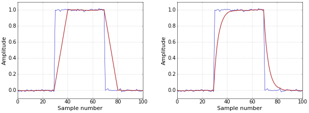
The article Why use Symmetrical FIR Filters with an Odd Length? mentiones that symmetrical FIR filters are linear phase. It shows the effect of a (linear phase) moving-average filter and a (nonlinear phase) single-pole IIR filter on a block pulse. Figure 1 from the mentioned article is repeated below for reference. One of the major effects of nonlinear phase delay is that rising and falling edges are affected differently. This is clear from Figure 1.
 Figure 1. Block pulse filtered with moving average (left) and single pole IIR (right) filters.
In this follow-up article, I simply want to show you what the phase response of these filters actually looks like.
Moving Average Filter: Linear Phase
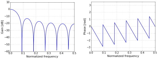
The moving-average filter is linear phase. Its frequency and phase response is shown in Figure 2. This linear phase delay follows from the mathematics, of course, but let’s go for an intuitive approach for now. Say that you have a 1 MHz sine and you put it through an all-pass filter with a delay of 1 μs, for example, an ideal cable. At the end of the cable, the sine will be delayed by exactly one cycle, since a million cycles per second translates into a duration of 1 μs for a cycle. This one cycle corresponds to \(2\pi\) rad of phase delay. Now take a second, 2 MHz, sine. Together, these two sines produce a combined waveform. If the filter does not distort this combined waveform, then it must be the same in the beginning and at the end of the cable. And, for this to happen, the 2 MHz sine must be delayed by two cycles, so that they keep the same phase relation with each other. Hence, the second sine must be delayed by \(4\pi\) rad, which is exactly a linear phase relation.
 Figure 2. Frequency (left) and phase (right) response of a moving-average filter.
Single-Pole IIR Filter: Nonlinear Phase
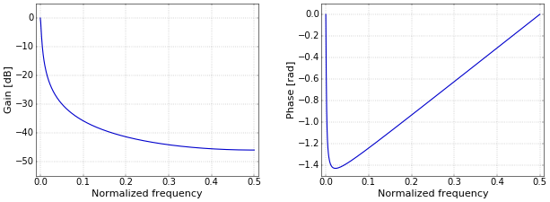
The single-pole IIR filter has nonlinear phase. Its frequency and phase response is shown in Figure 3 (for a decay value of \(d=0.99\)). The connection between the phase response and the actual distortion in the time domain is, alas, not so easily explained in an intuitive way as for linear phase. Even taking the additional step of plotting the group delay, which I won’t go into here, does not make the relation with the time-domain distortion obvious. For a number of practical applications, for example in digital communications, this is not really a problem, since the main goal there is to keep the group delay reasonably close to being constant anyway. An example of a practical way to achieve this in a receiver is adding an adaptive equalizer.
 Figure 3. Frequency (left) and phase (right) response of a single-pole IIR filter.
Add new comment